After completing the wireless setup for the motor driver, the actual robot came next. This, in my opinion, has to be the coolest part of this endeavor. I bought a gearbox set up from Sparkfun that was simple enough to assemble. The trick here was this gear box is designed to be used with two motors operating independently and I needed them to function simultaneously. This was easily fixed as the directions only called for one set screw to be used on one side of the box for the main drive shaft. By simply using the second set screw for the other side, both shafts will turn at the same rate, thus combining the torque of the two motors. One issue was noticed right away, the main drive shafts were clearly not long enough to directly attach to the sides of an 11 inch hamster ball purchased. For the moment, a coupling was created using two rubber corks as demonstrated below. The gearbox was attached to a piece of pine wood.
Gearbox Setup with Rubber Cork Couplings
The electronics were attached to the other side of the pine wood and the entire piece was placed inside the ball. The batteries were attached to the side with the gearbox and the wires were run around the board.
Full Electronics Setup
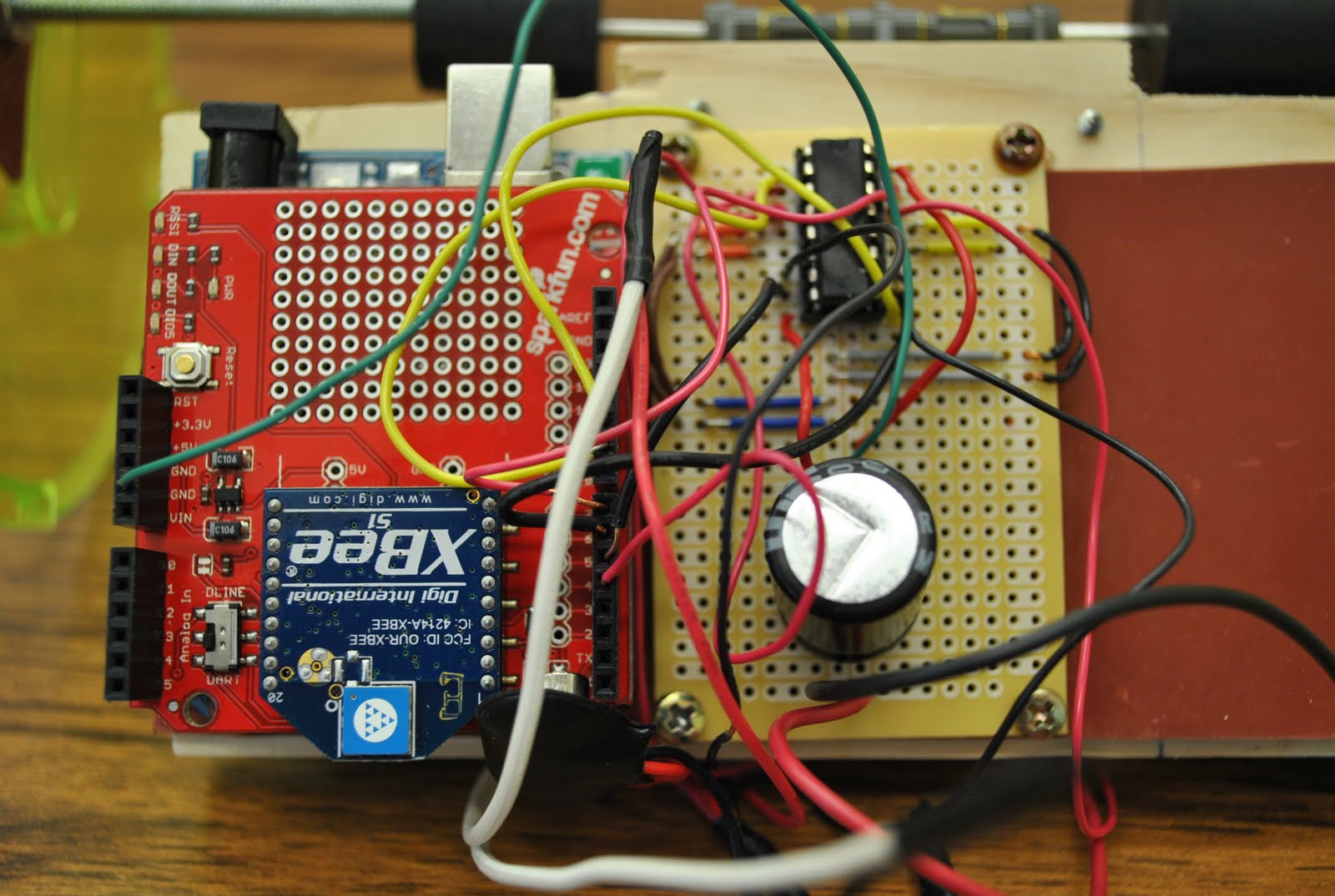
Electronics Closeup
Complete Circuit Diagram of Arduino/XBee and PCB/Motor Driver Setup
The motor driver circuit was migrated to a PCB board found at Radio Shack. A 16-pin retention pad was used to mount the motor driver IC chip to the board. This was certainly a challenge to solder. I originally chose to do this to save room and not have to mount a breadboard inside the ball, however, after soldering the PCB board, I think a breadboard mount would have been much simpler. At any rate, it was a learning experience and taught me quite a bit about soldering. In the process of wiring the PCB board, I decided to give the two motors connected to the gearbox a dedicated 9V voltage source, so one was wired up directly to the board with a second power source for the Arduino. This gave a significant power increase to the motors and when tested, nearly twisted my fingers off (I was seeing about how much torque was output). Ultimately, a single, rechargeable source will need to be used, but this works for now as a proof of concept. The two boards, the Arduino and PCB board were attached to the pine wood with a rubber pad as insulation to prevent the leads poking through the back of the boards from being damaged.
Complete Hamster Ball with Gearbox and Electronics Assembly Mounted Inside
While it is difficult to see, the entire gearbox assembly with the electronics is mounted inside the 11 inch hamster ball. Since the ball is so large, both sides of the ball have end caps that are removable for putting the hamster in either side. This worked out perfectly since the two end caps could be removed and attached to the drive shaft of the gear box (see photo above). Unfortunately, when initially tested, the weight of the electronics and mechanics inside the ball was so great the board dragged the bottom of the ball. This was caused solely from the couplings generated by the rubber corks. At this time, this has not been fixed. The following video demonstrates the concept, where the sides of the ball (the end caps) are rotated as wheels and when the mechanical setup is adjusted, will move the ball in the same fashion.
Several fixes will be addressed to the issues arisen from this project. The first one will be the drive shafts. A single drive shaft will be installed across the motors and a round aluminum shaft will be used in place of the all-thread. A hole will be drilled down the center of the thread and two set screws will be mounted on both sides for the gearbox drive shaft to slide into. Another hole will be drilled into the other end of the shaft to attach the sides of the ball to the shaft. This hole will be tapped for the screw to be flush with the side of the ball. To allow two axis of motion, a servo will be attached with a pendulum to swing from side to side changing the center of gravity, thus swinging the ball from side to side. All the electronics will be placed on one board. A motor driver kit especially designed for the Arduino micro controller may be used, or I may look at the hardware present on the Arduino board that I am not using and try to combine certain functions, possibly even generating a new board layout. This could then be ordered and everything will be present on one board.
So far, everything is ready for the first semester presentation I am giving on this project with my group on May 6th. The changes I mentioned above will hopefully be completed during the summer. Next semester, the server setup will be the primary goal having a final infrastructure as follows:
So far, the PC, Webcam, and Robot are functioning perfectly. The Robot will have to be driven through the Router and the User will have to communicate with the Router through a Server.


No comments:
Post a Comment