Labels

  • Senior Design Project
Showing posts with label Senior Design Project. Show all posts

Saturday, October 29, 2011

PCB Layout

Currently, the PCB is being soldered up in a rather quick fashion.  All the components were purchased from Mouser. The components are listed by part number on the following websites (and since my board is mostly a hack of these two boards, it only makes sense to purchase these parts): XBee Adapter and Arduino.  After about a week, all the parts came in and soldering has commenced.

PCB Board with some components
What can be seen here are two IC Sockets (also called retention pads), the linear 3v regulator (top right corner) and several other solder joints.  These other solder joints are the layer changes.  Since this board was constructed with both top and bottom traces, tiny holes were generated at the trace termination and the trace was continued on the other side.  A short pin from a male-to-male header was removed and inserted into this hole, cut off close to the board and the soldered in place.  This effectively serves the same purpose as the joints created by a professional PCB house (who was going for aesthetics anyways?).  This was probably the most tedious part, as each pad generated by the machine was extremely small.

Since this board contains both top and bottom traces, each component will need to be soldered on both the top and the bottom.  Some components, such as the 3V linear regulator in the top right corner, prove no problem in this action. Other components, like the IC Sockets, are quite challenging.  At the time of design, I had no idea how difficult it would be to solder in the socket on the the top side where the socket was inserted, and therefore, the components were inserted rather closely.  This made it quite difficult to solder into place.  After melting quite a bit of plastic on the socket (thankfully it only serves as insulation), a simpler method was discovered! By cutting multi-stranded wire into short segments, it can be inserted into the hole, laid flat along on top of the wire and then soldered into place.  This extends the leads through the hole where it can be soldered directly to the bottom of the board with the component.  This proved extremely helpful when soldering the XBee headers into place as the leads on the header barely fit through the hole to the bottom of the board.

Friday, October 7, 2011

The New Design

Production was started on the new hamster ball design over the last week.  Thanks to the lathe, two parts (that should have been completed in about 2 hours) were completed in about 10 hours.  This was due to the poor design of the lathe (and lack of CNC capabilities).

Four standard radial ball bearings were purchased to use in the shafts created on the lathe.  Pictures are below.
Finishing the end surface, preparing to cut hole for bearing
Drilling a hole  down the end to be tapped
Reducing the stock size
Finished product
Bearing inside stock

Friday, September 30, 2011

Some Progress

This week, much was completed.  One realization after my last post was the success of the current design.  While seriously lacking in quality, the design for the hamster ball is solid.  Serious tweaky will be needed in the future, but for now it will work.

For the time being, the servo is scrapped and only the drive system will be looked at.  News of a CNC lathe and mill soon to be added to our senior design lab prompted me to draw up the plans for this system in CATIA and convert to NC programming to execute on the lathe and mill.  This will hopefully fix a lot of the tweaking that will be needed and make the design more solid.  The files can be found here.

Much was accomplished on the programming side as well.  Earlier in the week, I successfully managed to control an LED on an Arduino using Processing and key duration.  The Arduino code and Processing code are written based on the duration of any key being pressed.  When a key is on the keyboard, the LED on the Arduino will slowly start to light up to the maximum value (bright).  When that key is released, the LED will turn off (or nearly off for this example).  It was discovered during the exploration of this code, that the Arduino was reading all incoming bytes of information as ASCII characters as similar with the XBee modules.  A similar implementation of the atoi() command was needed to convert the ASCII characters to integer values.  For further details, see this post.

This code was then modified to set a foundation for the Arduino software on the ball and the Processing code which will be within the web page.  The files can be found here and here.  They are not complete, nor have been tested, however, they show a start of some progress.

On another front, the electronics are being slowly condensed within one board.  Our instructor has helped with eliminating much of the unneeded hardware from the Arduino schematic and I have added the motor driver chip to the file.  A preview can be seen below.  The completed schematic will be uploaded when available.
Schematic of Arduino circuitry and motor drive unit
Still to be added to the schematic is the XBee setup and headers.  This will complete the schematic and hopefully allow us to begin arranging the PCB.

Friday, September 23, 2011

Updates


It has been some time since my last post.  Originally, much was intended to be accomplished over the summer months, completing the mechanical portion of the ball and finishing the programming side of the ball.  However, this did not occur.  Progress was once again reached with the start of the fall semester.

Starting the semester off, a new design was intended for the inner workings of the hamster ball.  The wood platform was cast aside for a new sleeker aluminum casing.  The rubber corks were removed and replaced with aluminum rod used as couplings.  To prevent the center mechanics from torqueing under weight, bushings were used to make the axis more rigid.  Pictures can be seen below:

 Fully Assembled Hamster Ball

 Gearbox Assembly Showing Aluminum Couplings and Bushings

 Closeup of the Bushings on both sides


Closeup of the attachment of the bushing


Servo and Pendulum Attachment with Electronics

The bushing was soldiered to a makeshift brass coupling where an oversized hole was punched to allow the bushing to move ever so slightly since the aluminum coupling is not perfectly centered.  This setup is troublesome and presents serious problems when disassembly is required (which it has been several times).

Another issue that was presented was the lack of space for the electronics (as you can see from the dangling XBee shield present in the electronics shots.  To solve this problem, it has been deteremined a combined circuit board, containing all the components needed on the Arduino with all the XBee shield components as well as the motor driver and its associated components.  Seeing as the Arduino plans are associated to Eagle files, the plans will most likely be compiled within.  Further research is being done on this.

The servo was attached to the top of the gearbox assembly with an adjustable arm to allow the center of gravity to be moved based on the battery used.  Through observation of this design, it was also noticed the pendulum may very well hit some of the electronic components on the XBee shield, thus furthering the need for a compiled board to be manufactured.

On the programming side of this contraption, much more progress has been made from my previous post. Originally, a joystick was used on a separate Arduino to drive the gearbox inside the ball.  This was great for a proof of concept (which it worked barely), however, the ultimate goal is to control the ball through the computer.  To do this, the controls need to be migrated to the computer.  Exploring the many options, Java was determined to be a very useful language seeing as it’s web-friendly and has a plethora of tools associated.  The Processing program was determined to be user-friendly from the programming aspect since it is C based and works with Java wonderfully.  Experimentation with this setup is well under way.   An example of controlling a window through processing code is shown below.

/* Color_Box draws a rectangle in a standalone window and fills rectangle
   based on how long any key is pressed.  This is done through a counter
   global variable.
*/


void setup()
{
  size(100,100); // Define size of window
}

int counter = 0; // Defines global variable for counting time key is pressed

void draw()
{
  
  rect(25, 25, 50, 50); // Draws rectangle inside window
  if (keyPressed == true) // Tests if key is pressed
  {
    counter++;
  } 
  else // Tests if key is not pressed
  {
    counter = 0;
  }
  
  /* Fills the contents of the rectangle with color associated
     to value of "counter."  This will cycle the colors from black to white. */
  fill(counter); 
}


Monday, May 2, 2011

Hamster Ball Robot

After completing the wireless setup for the motor driver, the actual robot came next.  This, in my opinion, has to be the coolest part of this endeavor. I bought a gearbox set up from Sparkfun that was simple enough to assemble.  The trick here was this gear box is designed to be used with two motors operating independently and I needed them to function simultaneously.  This was easily fixed as the directions only called for one set screw to be used on one side of the box for the main drive shaft.  By simply using the second set screw for the other side, both shafts will turn at the same rate, thus combining the torque of the two motors.  One issue was noticed right away, the main drive shafts were clearly not long enough to directly attach to the sides of an 11 inch hamster ball purchased. For the moment, a coupling was created using two rubber corks as demonstrated below.  The gearbox was attached to a piece of pine wood.
Gearbox Setup with Rubber Cork Couplings
The electronics were attached to the other side of the pine wood and the entire piece was placed inside the ball. The batteries were attached to the side with the gearbox and the wires were run around the board.
Full Electronics Setup
Electronics Closeup
Complete Circuit Diagram of Arduino/XBee and PCB/Motor Driver Setup
The motor driver circuit was migrated to a PCB board found at Radio Shack.  A 16-pin retention pad was used to mount the motor driver IC chip to the board.  This was certainly a challenge to solder.  I originally chose to do this to save room and not have to mount a breadboard inside the ball, however, after soldering the PCB board, I think a breadboard mount would have been much simpler.  At any rate, it was a learning experience and taught me quite a bit about soldering.  In the process of wiring the PCB board, I decided to give the two motors connected to the gearbox a dedicated 9V voltage source, so one was wired up directly to the board with a second power source for the Arduino.  This gave a significant power increase to the motors and when tested, nearly twisted my fingers off (I was seeing about how much torque was output).  Ultimately, a single, rechargeable source will need to be used, but this works for now as a proof of concept.  The two boards, the Arduino and PCB board were attached to the pine wood with a rubber pad as insulation to prevent the leads poking through the back of the boards from being damaged.
Complete Hamster Ball with Gearbox and Electronics Assembly Mounted Inside
While it is difficult to see, the entire gearbox assembly with the electronics is mounted inside the 11 inch hamster ball.  Since the ball is so large, both sides of the ball have end caps that are removable for putting the hamster in either side.  This worked out perfectly since the two end caps could be removed and attached to the drive shaft of the gear box (see photo above).  Unfortunately, when initially tested, the weight of the electronics and mechanics inside the ball was so great the board dragged the bottom of the ball.  This was caused solely from the couplings generated by the rubber corks.  At this time, this has not been fixed.  The following video demonstrates the concept, where the sides of the ball (the end caps) are rotated as wheels and when the mechanical setup is adjusted, will move the ball in the same fashion.
Several fixes will be addressed to the issues arisen from this project.  The first one will be the drive shafts.  A single drive shaft will be installed across the motors and a round aluminum shaft will be used in place of the all-thread.  A hole will be drilled down the center of the thread and two set screws will be mounted on both sides for the gearbox drive shaft to slide into. Another hole will be drilled into the other end of the shaft to attach the sides of the ball to the shaft.  This hole will be tapped for the screw to be flush with the side of the ball. To allow two axis of motion, a servo will be attached with a pendulum to swing from side to side changing the center of gravity, thus swinging the ball from side to side. All the electronics will be placed on one board. A motor driver kit especially designed for the Arduino micro controller may be used, or I may look at the hardware present on the Arduino board that I am not using and try to combine certain functions, possibly even generating a new board layout.  This could then be ordered and everything will be present on one board.

So far, everything is ready for the first semester presentation I am giving on this project with my group on May 6th.  The changes I mentioned above will hopefully be completed during the summer.  Next semester, the server setup will be the primary goal having a final infrastructure as follows:
So far, the PC, Webcam, and Robot are functioning perfectly.  The Robot will have to be driven through the Router and the User will have to communicate with the Router through a Server.

Tuesday, April 19, 2011

ASCII to Integer

The next most difficult setup was configuring the XBee modules to read values from a computer (ultimately another Arduino) and then write these values to the motor driver.  Through some basic exploration, it was determined the Arduino reads serial inputs as ASCII characters.  This was most troublesome as it presents some serious problems.  Ultimately, I wanted to pass integers to the Arduino using the serial port, values like 1, 505, and 1023.  Turns out, when the value "1" is passed through the serial monitor (just simply connecting via the USB port, the XBees were not used) the actual value the Arduino saw was the ASCII character "49." Forty-nine is not even close to full speed when connected to the motor driver.

Luckily, there is a nice function built into the standard library for the Arduino called ASCII to Integer.  atoi() is a nice function that will convert any single number from it's ASCII input to its equivalent integer value.  The first step in doing this, since we want to pass values with more than one character (i.e. 1023) we need to create a character array with five places.  The first four places will contain the four digits we want to convert and the last one will be set to null.  This will always guarantee there will be a blank value at the end to signify the end of an integer.  There are several ways to go about converting these values.  Here is the approach I used.

The first thing I looked at was how the values were handled at each input.  It was determined that at the end of each value (i.e. 15), a carriage return was inserted at the end of each line.  This value has an ASCII code as well and we do not want to convert it to an integer (it doesn't have an integer value).  Therefore a while loop was generated that would look for any new lines or carriage returns and check all values after. These ASCII characters are "13" and "10" (this can be looked up here).  Whenever a "13" or "10" is NOT received, then the ASCII values that follow will be read and stored in the character array generated earlier.  We will not touch the 5th place in the array as it will stay null.  If a "13" or "10" IS received, then the first value of the array will be set to null, "\0."  This will ensure there is no value stored to that variable and the motors will not move.

This sort of worked the first time around, however it turns out that whenever no value is sent to the Arduino's serial port, the ASCII value is "-1." This was corrected by adding an if statement looking to make sure the read value was not "-1."  Since the value "0" tended to produce errors (not completely sure why), I set an "old" variable that moved the older value to it before converting the new value just read. If the new value was a zero, the old value was used instead.

The final code used for the motor driver (which works with the XBee modules connected or just using the computer's serial monitor to pass values via USB cable):

#define switchPin 2 // switch input
#define motor1Pin 3 // Motor 1 leg 1 (pin 2, 1A)
#define motor2Pin 4 // Motor 1 leg 2 (pin 7, 2A)
#define motor3Pin 6 // Motor 2 leg 1
#define motor4Pin 7 // Motor 2 leg 2
#define enable1Pin 9 // Motor1 enable pin
#define enable2Pin 10 // Motor2 enable pin
#define ledPin 13 // Reset LED
#define slack 50 // Slack in joystick
int Y_axis_initial = 0; // Defines starting position of Y axis
char stickRead[5]; // Defines character size of 4 for reading serial input, 5th is null
int stickY; // Stick value
void setup()
{
  Serial.begin(9600);   //Turn on the Serial Port at 9600 bps
 
  // Sets scaling factors and reads initial value at program start
  int x;  // Sets storage variable for Serial.read()
  int i = 0; // Defines a counter for while loop
  Serial.flush();
  while(((x = Serial.read()) != 13) && ( x != 10 ));
  while( Y_axis_initial == 0 )
  {
    while(((x = Serial.read()) != 13) && ( x != 10 ))
    {
      if( x != -1)
      {
        stickRead[i++] = x;
      }
      stickRead[i] = '\0';
    }
    Y_axis_initial = atoi(stickRead);
  }
 
  // set the switches as an input:
  pinMode(switchPin, INPUT);
  // set all the other pins you're using as outputs:
  pinMode(motor1Pin, OUTPUT);
  pinMode(motor2Pin, OUTPUT);
  pinMode(motor3Pin, OUTPUT);
  pinMode(motor4Pin, OUTPUT);
  pinMode(enable1Pin, OUTPUT);
  pinMode(enable2Pin, OUTPUT);
  pinMode(ledPin, OUTPUT);
 
  // blink the LED 3 times. This should happen only once.
  // if you see the LED blink three times, it means that the module
  // reset itself,. probably because the motor caused a brownout
  // or a short.
  blink(ledPin, 3, 100);
}
void loop()
{
  // Reads position of A0 and A1 (X and Y axis)
  int x;  // Sets storage variable for Serial.read()
  int i = 0;  // Defines a counter for while loop
  while( ( ( x = Serial.read() ) != 13 ) && ( x != 10 ) )
  {
    if( x != -1 )
    {
      stickRead[i++] = x;
    }
  
  }
  stickRead[i]='\0';
  int oldstick = stickY;
  stickY = atoi(stickRead);
  if( stickY == 0 )
  {
    stickY = oldstick;
  }
 
  int minus_Y = abs(stickY-510)/2;
  int plus_Y = abs(stickY-513)/2;
  // Reads the position of Y axis and determines direction and speed
  if (stickY < Y_axis_initial-slack)
  {
    analogWrite(enable2Pin, minus_Y);
    digitalWrite(motor3Pin, HIGH); // set leg 1 of the Motor2 high
    digitalWrite(motor4Pin, LOW); // set leg 2 of the Motor2 low
    analogWrite(enable1Pin, minus_Y);
    digitalWrite(motor1Pin, HIGH); // set leg 1 of the Motor1 high
    digitalWrite(motor2Pin, LOW); // set leg 2 of the Motor1 low
  }
  if (abs(stickY - Y_axis_initial) < slack)  // Sets deadspace on stick
  {
    digitalWrite(enable2Pin, LOW);
    digitalWrite(enable1Pin, LOW);
  }
  if (stickY > Y_axis_initial+slack)
  {
    analogWrite(enable2Pin, plus_Y);
    digitalWrite(motor3Pin, LOW); // set leg 1 of the Motor2 low
    digitalWrite(motor4Pin, HIGH); // set leg 2 of the Motor2 low
    analogWrite(enable1Pin, plus_Y);
    digitalWrite(motor1Pin, LOW); // set leg 1 of the Motor1 low
    digitalWrite(motor2Pin, HIGH); // set leg 2 of the Motor1 high
  }
}
//blinks an LED
void blink(int whatPin, int howManyTimes, int milliSecs)
{
  int i = 0;
  for ( i = 0; i < howManyTimes; i++)
  {
    digitalWrite(whatPin, HIGH);
    delay(milliSecs/2);
    digitalWrite(whatPin, LOW);
    delay(milliSecs/2);
  }
}

Thursday, April 14, 2011

H-Bridge Configuration

So, the ultimate goal here is to be able to drive a set of two motors through a gear box to convert the direction and to create one axis of rotation within a hamster ball.  The ball will act as the wheel and the drive components will be inside the wheel.  In order to do this, I needed to drive a couple of motors with an Arduino.  Turns out, the output current from the Arduino is not sufficient to power even one motor, much less two.  Some FETs are the solution and through some research online, a nice H-Bridge was found that has all the FETs set up for me ready to go! Sparkfun has some available for about $2.35, which isn't too bad. The datasheet gives the voltage range as 4.5V all the way up to 36V at 1A.  This should be more than enough power to drive the ball.

I found a nice set of instructions online for how to set this up for one motor here.  For testing it out and understanding how the H-Bridge functions, this tutorial was quite helpful.  What I needed, was two motors to drive instead. This was a matter of simply copying the existing code for one side and mirroring it to the other side.  Connecting two potentiometers, one for motor one, and one for motor two, the speeds could be controlled by setting the "enable" pins on the H-Bridge as an analogRead() function.  The enable pins (pin 1 and 9 on the H-Bridge) control the speed of the motor.  Depending on the voltage supplied to the enable pins (between 0 and 5V) will determine the speed.  this is done using pulse width modulation since the Arduino can only write a HIGH (5V) or a LOW (0V) to any pin.  A very good description of how this works is on Wikipedia.  Essentially, the Arduino will write a HIGH value followed by a LOW value, each for a certain length of time where the average value becomes  the desired voltage.  For example, writing a HIGH value for 2.5 seconds and a LOW value for 2.5 seconds will give you an average voltage of 2.5V.

Next, I decided to purchase a Joystick shield from Sparkfun (here).  The goal here was to use the joystick to control the speed and direction of the motor instead of two potentiometers and a pushbutton switch.  The hardest part on configuring the joystick portion was setting the center point.  One would think the center point would be 512 since the input ranges from 0 to 1023, however, on the X-axis, the center is 505 and the Y-axis is 489.  Despite this annoying set back, the simple fix was to read the value of the stick in the initial setup when the Arduino starts up.  Ultimately, the directions had to be divided so all positive axes movement resulted in clockwise rotation and all negative movement resulted in counter-clockwise motion.  An example of this is below:


That version of the program does not function correctly, it needed some debugging.  Turns out, the values were being read so quickly the joystick didn't have time to adjust and send the values (mechanical problems).  This was fixed by setting a "deadspace" into the program.  This deadspace was a range where the joystick could move on each axes and the value would not be translated.  In other words, it would write a LOW to the pins.

The following code displays the final code used for this joystick setup.  There are some bad programming habits within it, including calculations and reading during each condition, however, for the purposes of testing out the joystick, it functioned perfectly.  The next step, setting up the two XBees to run the joystick wirelessly, has corrected these values.
// X axis is A0
// Y axis is A1
#define switchPin 2 // switch input
#define motor1Pin 3 // Motor 1 leg 1 (pin 2, 1A)
#define motor2Pin 4 // Motor 1 leg 2 (pin 7, 2A)
#define motor3Pin 6 // Motor 2 leg 1
#define motor4Pin 7 // Motor 2 leg 2
#define enable1Pin 9 // Motor1 enable pin
#define enable2Pin 10 // Motor2 enable pin
#define ledPin 13 // Reset LED
#define slack 50 // Slack in joystick
float joy0;  // Defines scaling factor for joystick A0
float joy1;  // Defines scaling factor for joystick A1
float joyA0; // Defines starting position of X axis
float joyA1; // Defines starting position of Y axis
void setup()
{
        // Sets scaling factors at program start
        joy0 = 1023/analogRead(A0);
        joy1 = 1023/analogRead(A1);
        // Determines and reads starting positions of X and Y axis
        joyA0 = analogRead(A0);
        joyA1 = analogRead(A1);
      
        // set the switches as an input:
pinMode(switchPin, INPUT);
// set all the other pins you're using as outputs:
pinMode(motor1Pin, OUTPUT);
pinMode(motor2Pin, OUTPUT);
pinMode(motor3Pin, OUTPUT);
pinMode(motor4Pin, OUTPUT);
pinMode(enable1Pin, OUTPUT);
        pinMode(enable2Pin, OUTPUT);
pinMode(ledPin, OUTPUT);
      
        // set enablePin high so that motor can turn on:

// blink the LED 3 times. This should happen only once.
// if you see the LED blink three times, it means that the module
// reset itself,. probably because the motor caused a brownout
// or a short.
blink(ledPin, 3, 100);
        Serial.begin(9600);   //Turn on the Serial Port at 9600 bps
}
void loop()
{
        // Reads position of A0 and A1 (X and Y axis)
        int stickX = analogRead(A0);
        int stickY = analogRead(A1);
//        Serial.println(stickX);

        // Used to determine position of joystick
//        Serial.print("X:");
//        Serial.print(stickX);  // Prints original X
//        Serial.print(",Less:");
//        Serial.print(abs(stickX-510)/2);  // Less than X center
//        Serial.print(",Greater:");
//        Serial.print((stickX-512)/2);  // Greater than X center
//        Serial.print(" Y:");
//        Serial.print(stickY);  // Prints original Y
//        Serial.print(",Less:");
//        Serial.print(abs(stickY-510)/2);  // Less than Y center
//        Serial.print(",Greater:");
//        Serial.println((stickY-513)/2);  // Greater than Y center
      
        // Reads the position of A0 and determines direction and speed
        if (stickX < joyA0-slack)
        {
          analogWrite(enable1Pin, abs(stickX-510)/2);
          digitalWrite(motor1Pin, HIGH); // set leg 1 of the Motor1 high
 digitalWrite(motor2Pin, LOW); // set leg 2 of the Motor1 low
        }
        if (abs( stickX - joyA0 ) < slack)  // Sets deadspace on stick
        {
          digitalWrite(enable1Pin, LOW);
        }
        if (stickX > joyA0+slack)
        {
          analogWrite(enable1Pin, (stickX-512)/2);
          digitalWrite(motor1Pin, LOW); // set leg 1 of the Motor1 low
          digitalWrite(motor2Pin, HIGH); // set leg 2 of the Motor1 high
        }
      
        // Reads the position of A1 and determines direction and speed
        if (stickY < joyA1-slack)
        {
          analogWrite(enable2Pin, abs(stickY-510)/2);
          digitalWrite(motor3Pin, HIGH); // set leg 1 of the Motor2 high
 digitalWrite(motor4Pin, LOW); // set leg 2 of the Motor2 low
        }
        if (abs(stickY - joyA1) < slack)  // Sets deadspace on stick
        {
          digitalWrite(enable2Pin, LOW);
        }
        if (stickY > joyA1+slack)
        {
          analogWrite(enable2Pin, (stickY-513)/2);
          digitalWrite(motor3Pin, LOW); // set leg 1 of the Motor2 low
 digitalWrite(motor4Pin, HIGH); // set leg 2 of the Motor2 low
        }
}
//blinks an LED
void blink(int whatPin, int howManyTimes, int milliSecs)
{
int i = 0;
for ( i = 0; i < howManyTimes; i++)
{
digitalWrite(whatPin, HIGH);
delay(milliSecs/2);
digitalWrite(whatPin, LOW);
delay(milliSecs/2);
}
}

Tuesday, April 12, 2011

XBee and Arduino Configuration

I was extremely surprised to find how little information and tutorials there are on how to configure two XBees to communicate, either using a computer to Arduino set up or Arduino to Arduino set up.  To be honest, the entire set up is really quite simple.  Essentially, the two communicate using the serial read and serial write abilities of the computer and Arduino.  Unfortunately, the only easy way to configure the XBee modules is to use a Windows only application called X-CTU which is available from the Digi website here.

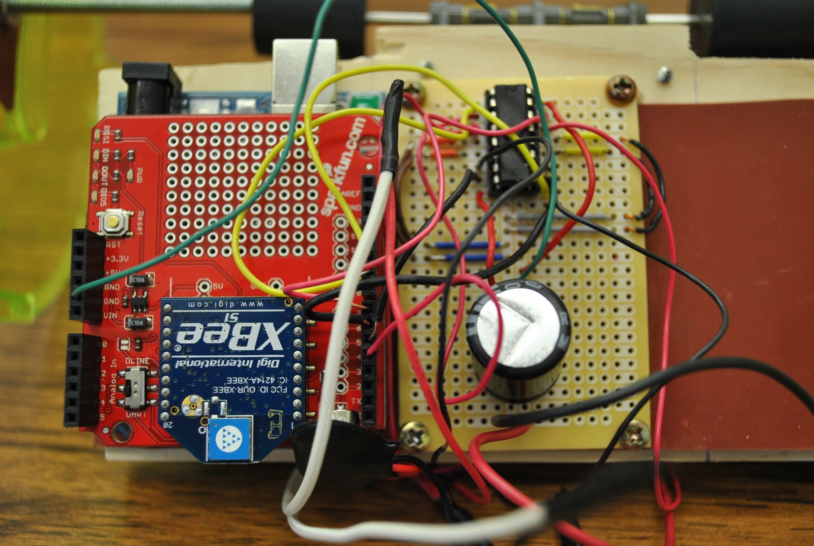
Alright, so you have X-CTU installed on a Windows machine, two XBee modules, a USB interface and the XBee shield (this can be found here on the Sparkfun website as a retail kit), now how do you make it work? First, you will need to configure one XBee to be the coordinator (the sender).  Plug the XBee module into the USB Explorer (or any USB interface device, I used this one) and then into the computer.  If you are running Windows Vista or higher, the drivers should already be installed to read this device. If not, or you are running Windows XP, you will need to obtain the FTDI drivers from 
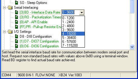
here, just select your operating system and follow the instructions.  Simply put, these drivers allow the computer to read your USB device as a serial port since the XBee modules act as serial modems.  Next, we will need to read the XBee module.  After plugging in the USB device, open the X-CTU application and leaving all the settings at their defaults, go to the modem configuration tab and click on "Read."  This will read the current data on the XBee module and display then in a screen much like this one:
So what do all these values mean?  For a thorough overview with a complete description of each command you can check out the XBee manual here. I found this to be of very little value, especially if you're looking to just configure the modules for basic use.  For this example, we will only be passing integers across the network, therefore, the default packet sizing will suffice.  If we were to pass, say Arduino programs across the network, we would need to set the packet size much larger to allow larger files and data rates to transfer.

CH:  The CH (Channel) is simply which channel you wish to operate.  For the purposes of this demonstration, the default "C" channel.  It is important that which ever channel you choose to use, that both XBee modules are set on the same channel.
ID:  The ID (Pan ID) is the numeric value of the network.  This can be any 4 digit number as long as the ID on both modules is set the same.
DL: The DL (Destination Address Low) is the address of the module you are sending data to. The DL of the sender will be the MY of the receiver.
MY: The MY (16-bit Source Address) is the address of the module which is being used.  This functions similar to the way your IP address works on your computer.  This is the address which is needed to connect to this device.


A2: A2 (Coordinator Association) is where you set whether this module is a coordinator, in other words, if it is a sender of data or a receiver.  A sender is 1 and a receiver is 0.


BD: The Interface Data Rate (BD) is the baud rate at which the serial port is used.  For use on the Arduino, this is the value which the Serial.begin(...) command is opened on.  The default value is set to 3-9600.  This is the most common and unless you are needing to read at a faster value, will do just fine for most Arduino applications.

To configure the first XBee module for use as a coordinator, simply change the following settings:
  1. ID = 1113
  2. DL = 1234
  3. MY = 5678
  4. A2 = 1
  5. BD = 3-9600
We are setting the Pan ID to 1113, the Destination Address to 1234, the 16-bit Source Address to 5678 and we are enabling this device as a coordinator.  We are also setting the baud rate to 9600 bps for this example.  Once these values have been set, we need to write this data to the module.  To do this, simply click the "Write" button.  If everything has been set up properly, there will be no errors.  If errors are present, check to make sure the baud rate on the first tab is set up properly in X-CTU. Make sure it is set to the baud rate you are setting the module to.

Next we will configure the receiver.  This can be done by exiting out of X-CTU, switching out the XBee modules (keep track of which one is which as they are not interchangeable). Open X-CTU again, going to the modem configuration tab and reading the module.  This time we will set the attributes as follows:
  1. ID = 1113
  2. DL = 5678
  3. MY = 1234
  4. A2 = 0
  5. BD = 3
Here, we are setting the Pan ID the same as the previous since we want this device to read data on the same network as the coordinator.  The Destination Address will be the same as the coordinator here so the device can communicate back (if you want to send data back and forth).  The 16-bit Source Address is the same as the Destination Address on the coordinator module.  This allows the other device to see this as the destination of the data it's sending.  We do not want to enable this device to coordinate, so we leave A2 as zero. We leave the baud rate as 3-9600.

We need to write these attributes to the module by going to the "Write" button just as we did for the coordinator.

Now these two devices are set up to communicate one way from either the computer or an Arduino to another computer or Arduino.  Let's test to make sure it works.  First you will need to solder up the XBee shield for the Arduino and then plug that into the Arduino.  Upload the following code to the Arduino before inserting the XBee into the slot:
void setup()
{
   Serial.begin(9600);
   Serial.flush();
   pinMode(13, OUTPUT);
}
void loop()
{
   char val = Serial.read();
   if(val == 'a')
   {
      digitalWrite(13, HIGH);
   }
   if(val == 'b')
   {
      digitalWrite(13, LOW);
   }
}
This program will let us pass serial values to the Arduino using the built in serial monitor within the Arduino GUI.  After writing this program to the Arduino memory, insert the sending XBee module into the USB explorer and connect it to the computer.  Make sure the proper device is selected under the serial port within the Arduino GUI interface.  Open the serial monitor.  Now connect the receiving XBee module to the Arduino by placing it within the shield and connect an external power supply to the VIN and GND ports.  You can not power the Arduino using a USB cable since the Arduino is seen as a serial device.  There will be a conflict between the serial USB and the XBee.  Next, type in the window an "a" without quotations and you should see the LED on pin 13 (connected on the board already) light up.  If you type a "b" and send it, the LED should turn off.

If you want to have two Arduinos connect to each other,  you can write a program to pass values through the sending XBee modules (you will need another XBee shield to make this work) to the other Arduino.  One way to check this is working is to flash a program that writes an "a" and then a "b" every second to the serial port.  The LED on the receiving Arduino should flash on and off every second.

Friday, April 8, 2011

Senior Design Project

Welcome to my Senior Design Project page.  Here is a short description of the design the group and myself are currently working on:

This project's original goal is to design and construct a solution to a problem or idea students develop to demonstrate the understanding of concepts discussed and learned throughout the university's education.  My group really just wanted to build a robot (isn't this the coolest dream of any group of engineers?), so we decided to do just that.  What sets this robot apart from others is it's unique client el: Dog Owners.  Ultimately, this robot will allow users, dog owners, to play with their dogs while away from home over the internet.  They will be able to interact with the robot and visually identify with the dog.  The main goal (at this time) is to control a two-axis, motorized hamster ball wirelessly over the internet.  This robot will eventually be encased in a "kong-like" rubber, vary similar to the dog toys of the same name, thus making it "dog-proof."

At this time, I have finally been able to get two XBee Series 1 Modems to communicate appropriately, the computer as the coordinator and an Arduino as the end device.  I will post directions on how to do this later.  I was quite surprised to find in my research of the XBee modules, how few tutorials or even how little information on how they function.  One could read the manual and learn what all the abbreviations mean, but still not be able to have complete communication.  At any rate, I am able to pass integers through the computer to the Arduino using the Serial.read() function and a for loop in conjunction with the atoi() function to calculate the integer values (from 0 to 9999).